What and Why
For my final project, I set out to create a handheld object that could react to different qualities of touch on its surface. The user will attempt to convey emotions through his or her touch, resulting in different qualities of touch on this object. This object can then be used in formats such as theatrical performance as a tangible interface for expressing, projecting, and controlling some aspects of the user’s desired emotional content.
The functionality of this object was inspired by a performance issue in the upcoming opera Death and the Powers, which the Opera of the Future group is developing. In this opera, the main character, Simon Powers, early on uploads his consciousness into a computer system. Thus, the physical body of the actor leaves the stage; instead, the entire set, through robotics and projection, begins to perform as the character. However, it is necessary for this performance to be a live performance influenced by the real actor's performance offstage. How can the actor intentionally convey a sense of his emotional state to the systems running the set?
For this version of this object, I chose to map the quality of the user's touch to different LEDs.
The Construction Process
Some of the materials that I thought might be useful in this process of creating this object:
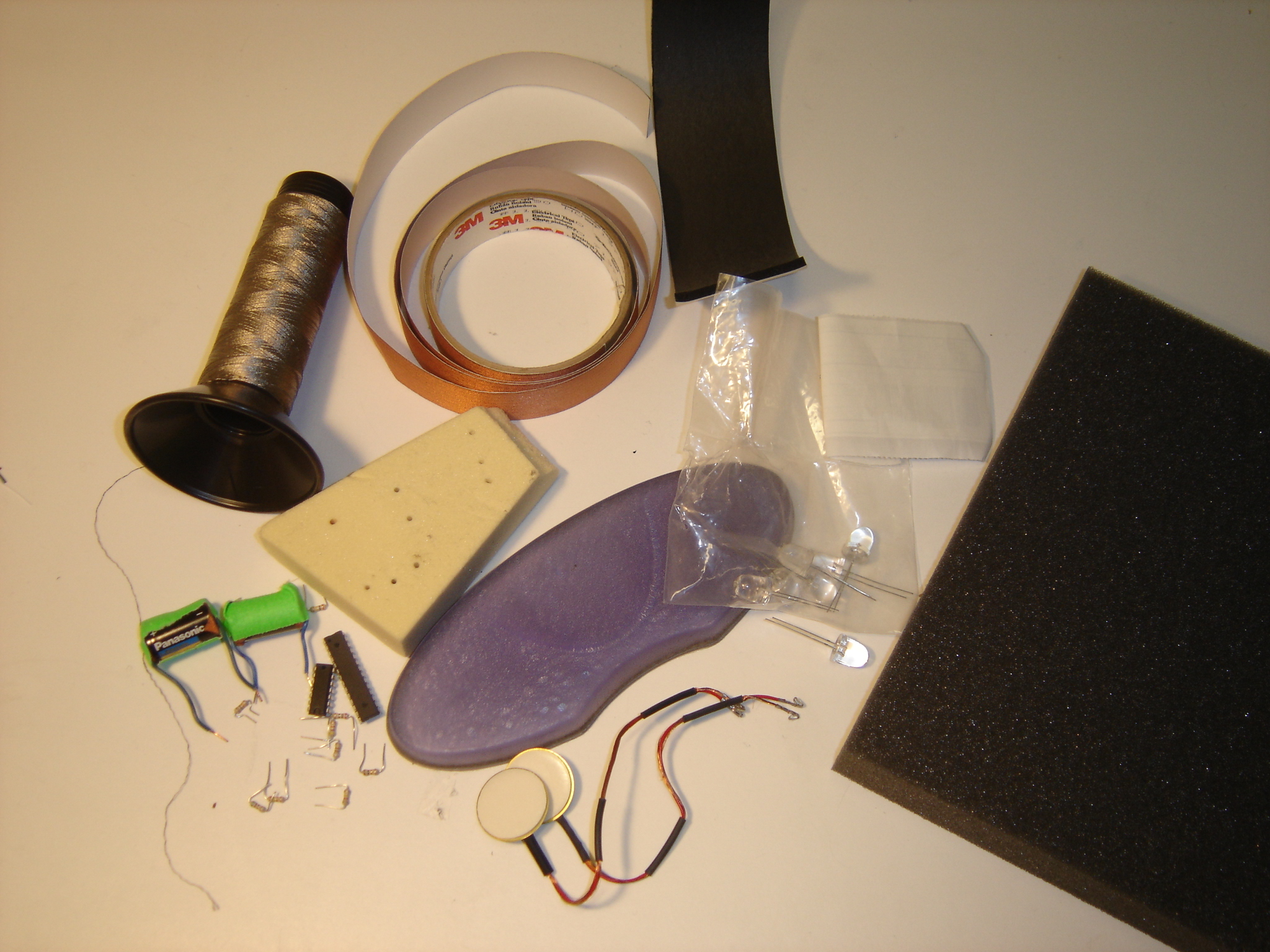
I needed sensors that could pick up different pressures or different positions. I looked at linear potentiometers, but did not get results that were particularly interesting -- the position at which one touches an object does not seem to be intuitively linked to emotional state. I realized that I was most interested in measuring quality of touch through pressure.
I constructed soft, squeezable pressure sensors using conductive foam, inspired by the foam sensors described in Gordan McComb's Robot Builder's Sourcebook.
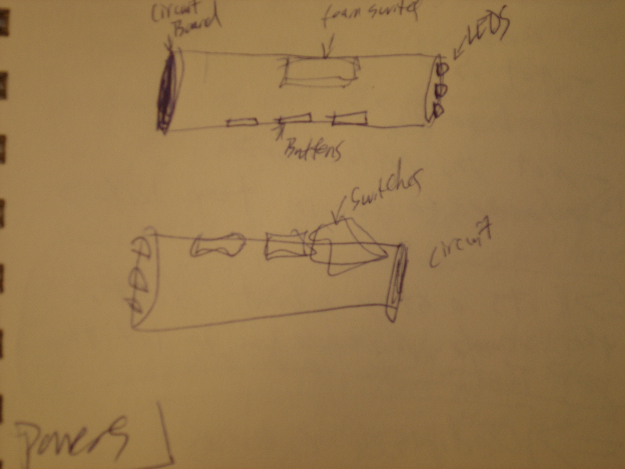
My sensors are made by layering:
1) A piece of non-conductive foamy tape
2) A piece of flexible copper tape with a wire soldered to it
3) A piece of conductive foam
4) Another piece of copper tape (with an attached wire), perpendicular to the first
5) A second piece of non-conductive foam tape
The layers are held together by black electrical tape.
I started by cutting two pieces of a thin, slightly compressible foam tape to serve as the outer layers of the sensor.
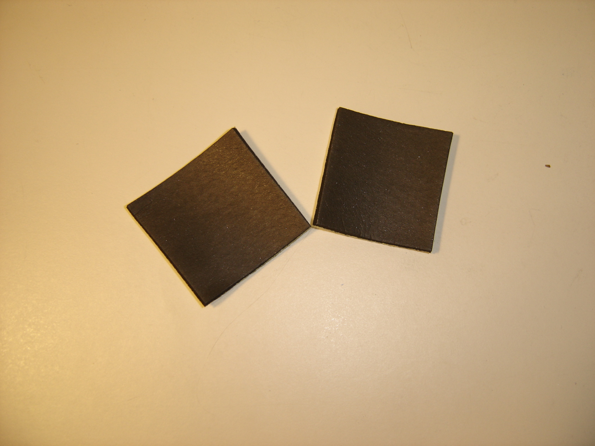
I next attached two pieces of flexible copper tape to these foam pieces.
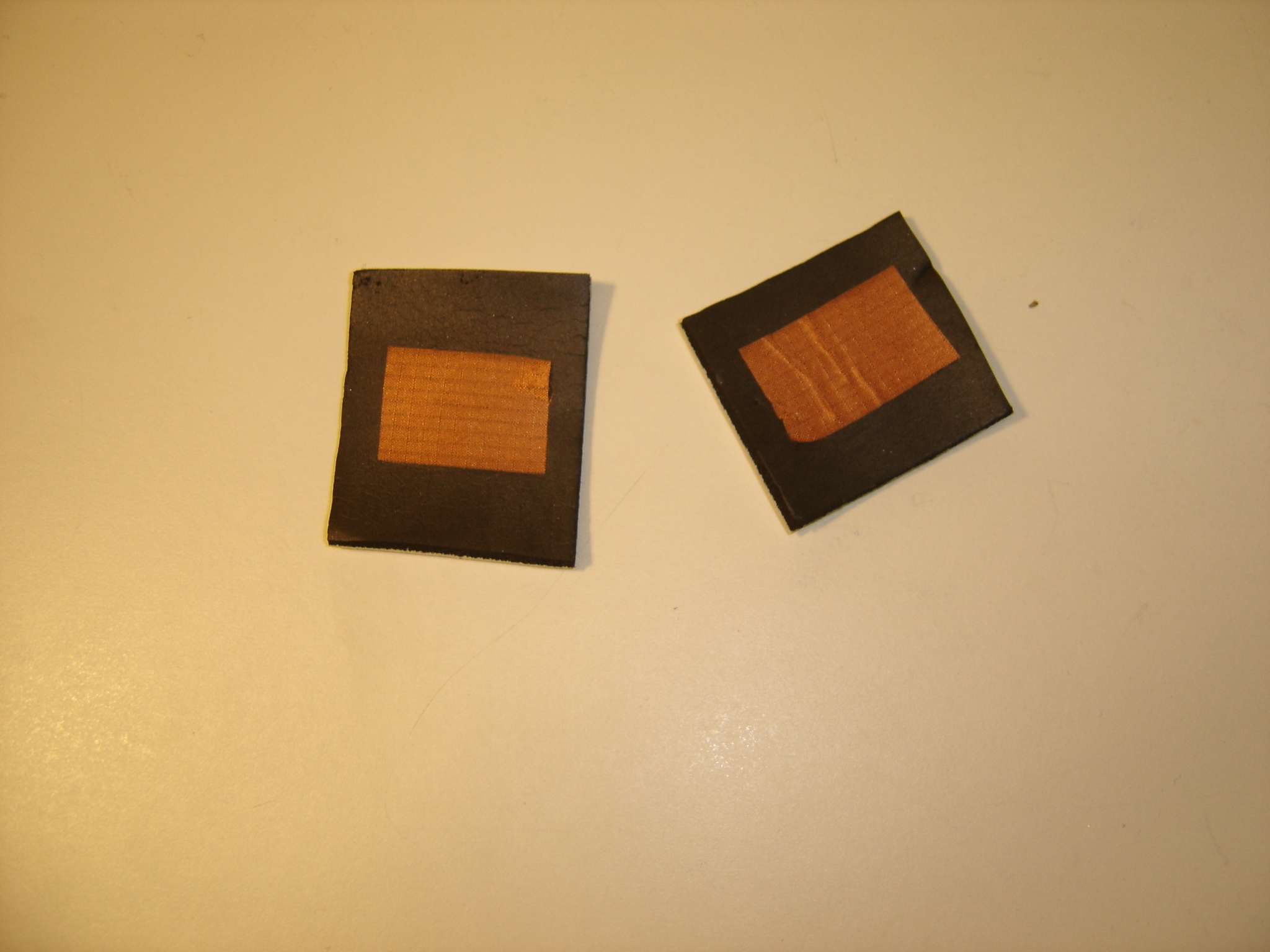
I soldered wires to each piece of copper tape.
I then put a piece of conductive foam (the foam that electronic components are packed with)
between the two copper layers.
The finished sensor:
The resulting combination creates a fairly soft, squeezable sensor with a wide range of readings.
With a 2.8V input, using an 11K resistor to ground for the voltage division
the output of the sensor varied from approximately 25mV to approximately 2V.
The completed sensors:
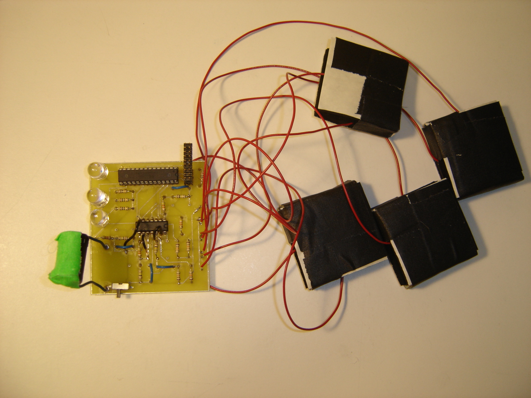
I then designed a circuit that incorporated four of these sensors, each as the variable resistor in a voltage divider construction. The resulting signals were amplified and buffered with an op-amp, then sent to four of the ADC ports on an Atmega88P microcontroller. Three 10mm LEDs were hooked up to the microcontroller outputs.
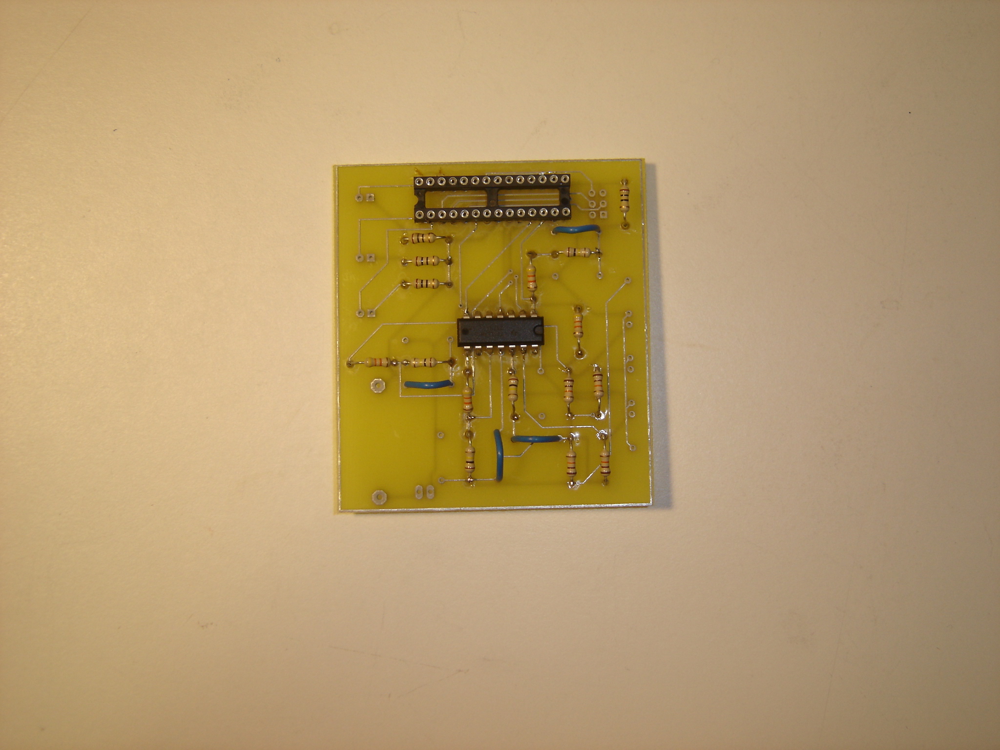
The final Eagle schematic and board files (with a few edits by Sajid):
My board was then sent out to be manufactured.
![]()
When I got back my manufactured circuit board, I set to work at attaching the necessary components.
I ended up not incorporating voltage biasing on the opamps as I had originally planned in my
schematic, as the voltage from each sensor when no pressure was applied
was slightly different and all were very close to 0V. I did, however, use the opamps to amplify
the signal.
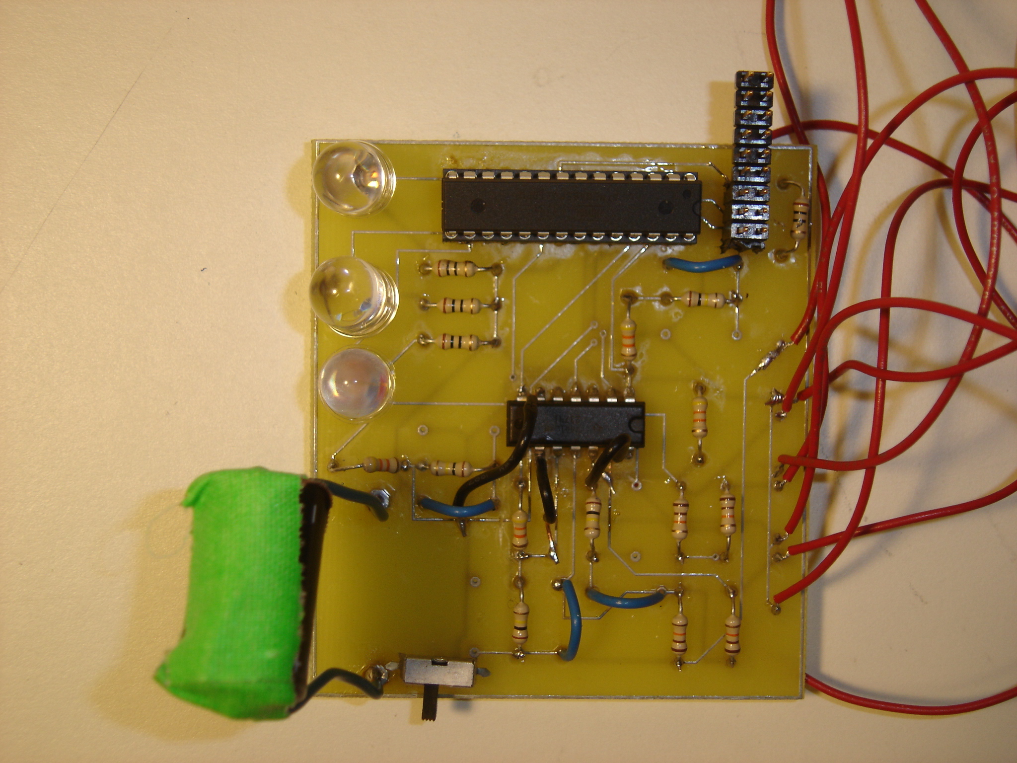
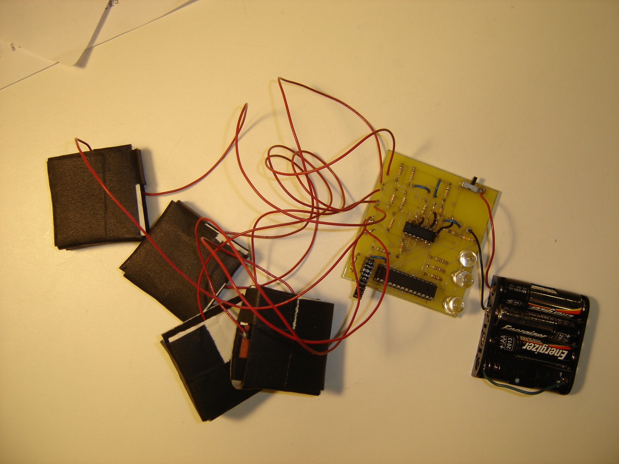
The board with all sensors attached:
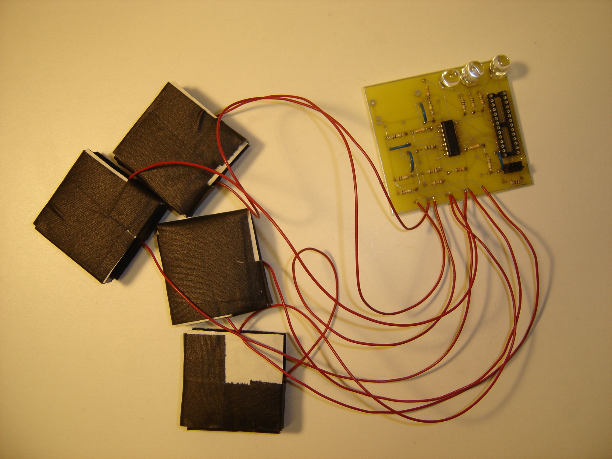
The board close up:
I wrote a C program for the microcontroller that periodically cycled through the active analog inputs, saved the current values, and performed logic based on the four current input signals to determine which LED to turn on.
Testing the sensor and the programming.
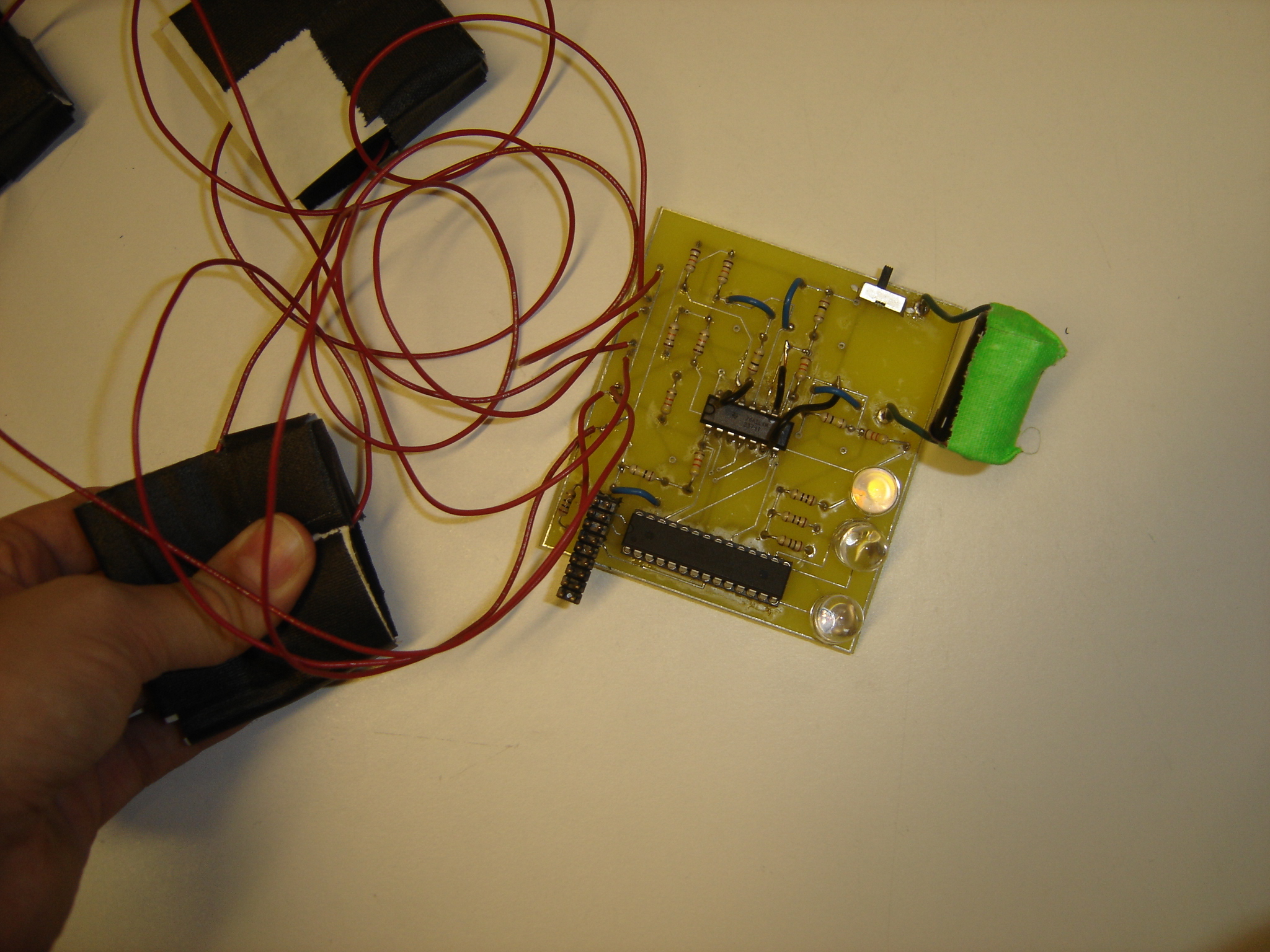
However, I ran into three issues in the process of programming and testing my code. First, and most significantly, I had made an error on the schematic that meant three of my four opamps had the positive and negative inputs reversed. I had to cut some traces (using a mat knife and screwdriver) and re-attach those traces to the correct inputs with jump wires.
The re-worked board:
Second, I found that the battery I was using, a 3V battery that actually provided about 2.8V, while it was strong enough to power the ompamp and the microcontroller, did not provide enough voltage for the microcontroller to output a "high" value that would turn on the LEDs brightly. While the LEDs did turn on, they could barely be seen.
I chose to use a different battery source. Since I needed something between 2.5V and 5.5V for the
microcontroller to run, I adapted a 4AA battery holder to hold 3AA batteries (output voltage between
4.75 and 5V) by running a wire from terminal to terminal of the holder for the fourth battery.
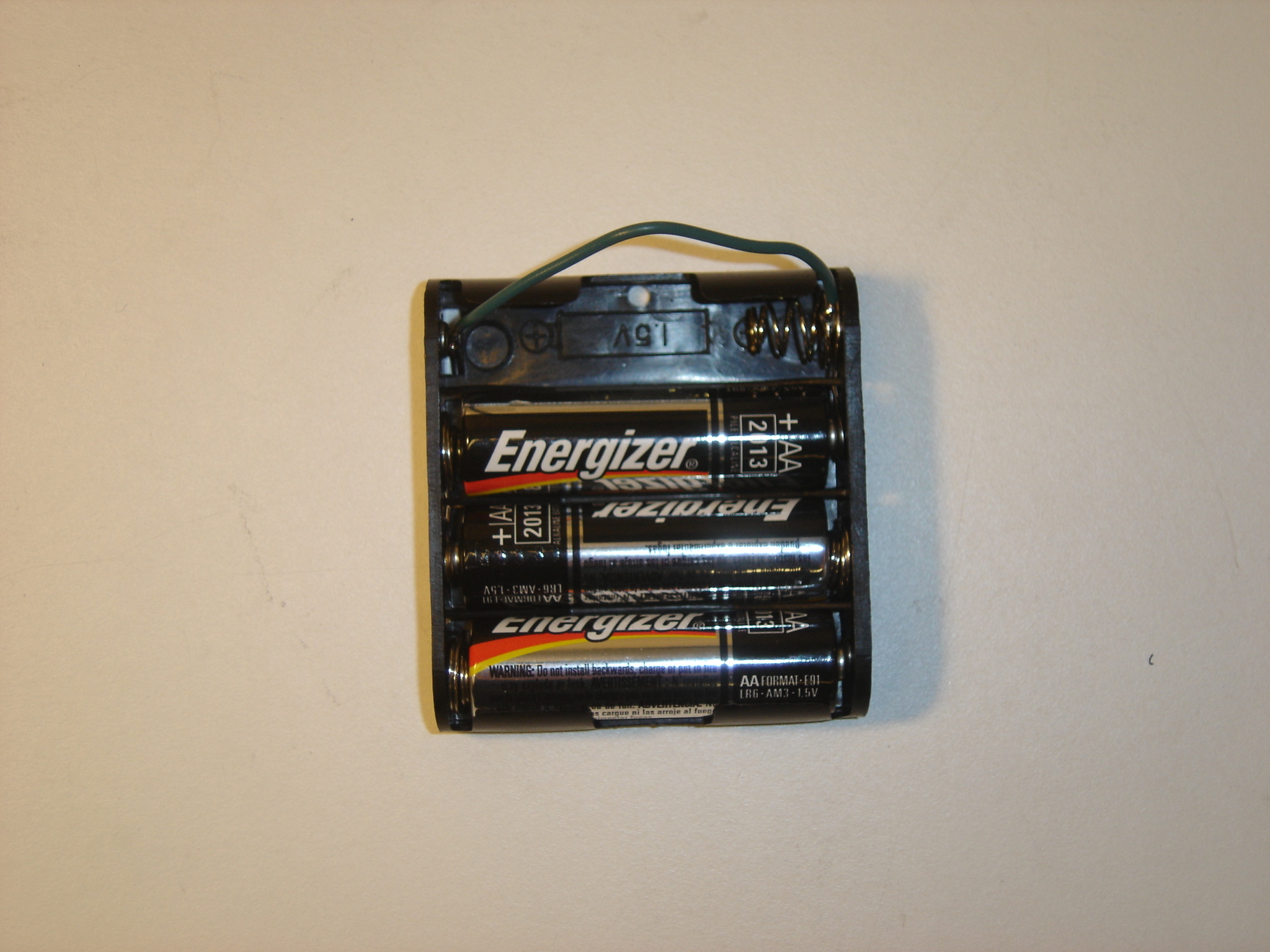
The circuit board with the new battery pack.
Third, my opamp amplification resistors needed to be adjusted to give me the widest range of possible values. I'd amplified the sensor output too much, which resulted in clipping the output range.
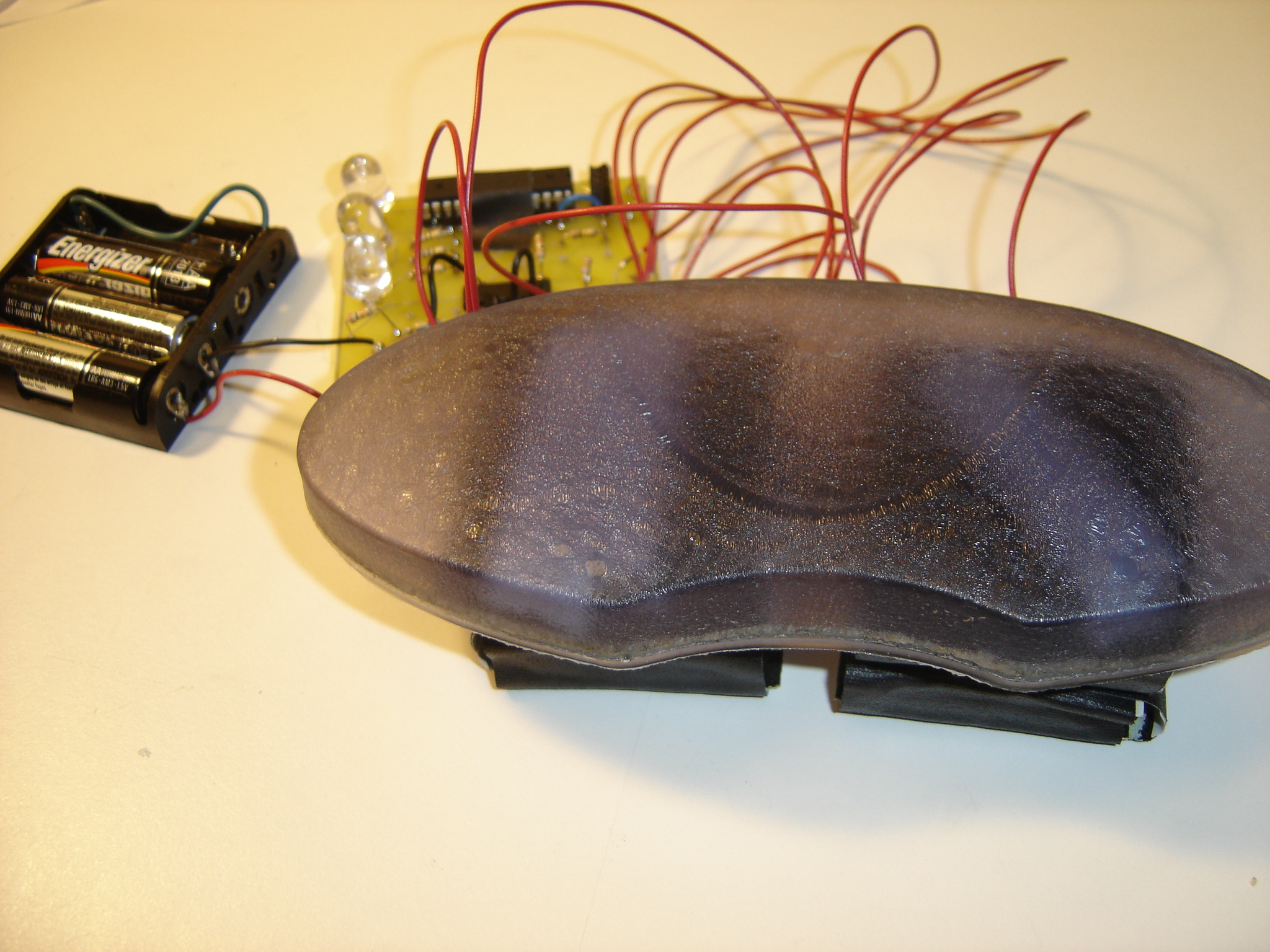
Once I had addressed these issues, I finished assembling my object. With the larger size of battery
pack and a larger circuit board than I'd anticipated, I decided to make this an object that would
rest on the table, rather than be handheld. I used an old gel mouse wristpad as the base, since I liked its
interesting texture and pliability. I taped the conductive foam sensors to the bottom of the gel pad.
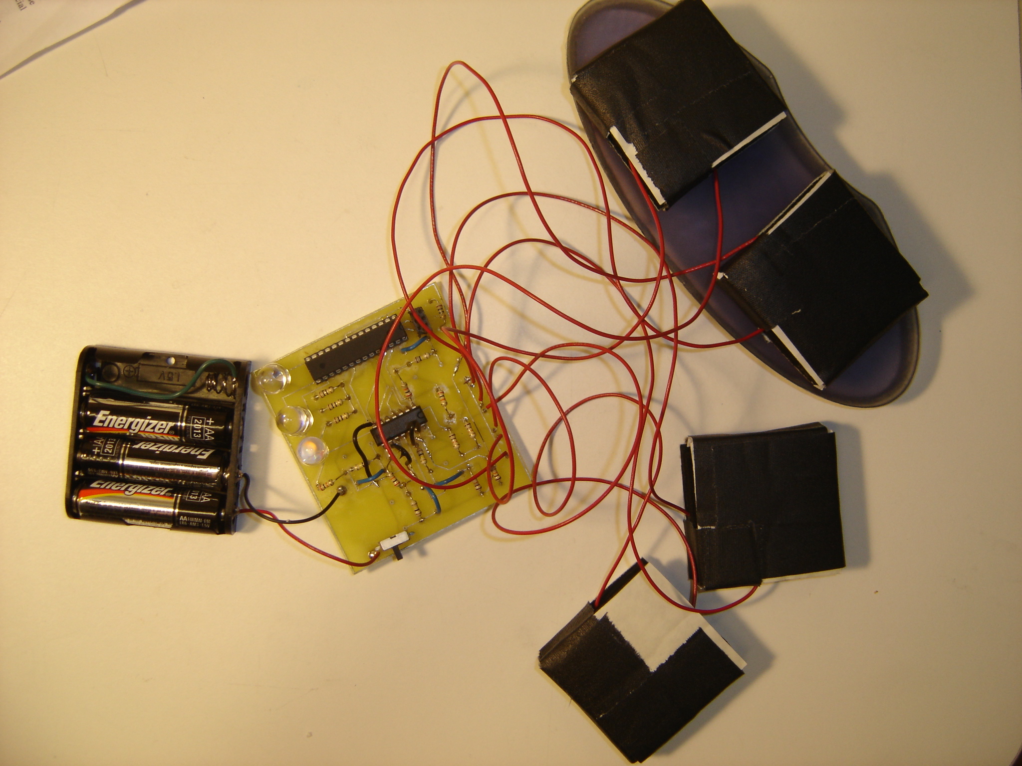
The object with all sensors attached to the gel pad.
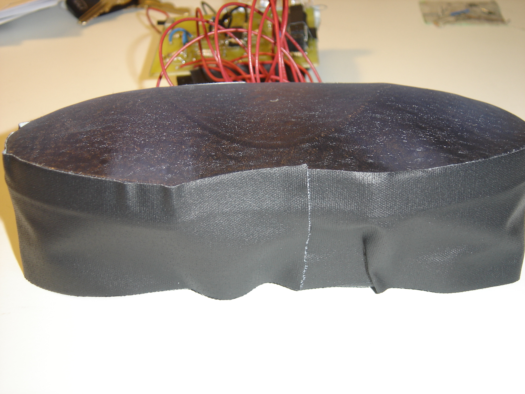
I then put black electrical tape around the sides of the pad to hold everything in place.
I also rewrote some of the microcontroller code so that the program requires sensors on both sides of the pad to get similar amounts of pressure in order to trigger an LED. Pressing significantly harder on one side than the other will not turn on the lights. With no pressure or a light touch from the user, the green LED turns on. With slight pressure (energetic touch), the yellow LED turns on. With hard pressure (angry touch), the red LED turns on.
Results
The completed device: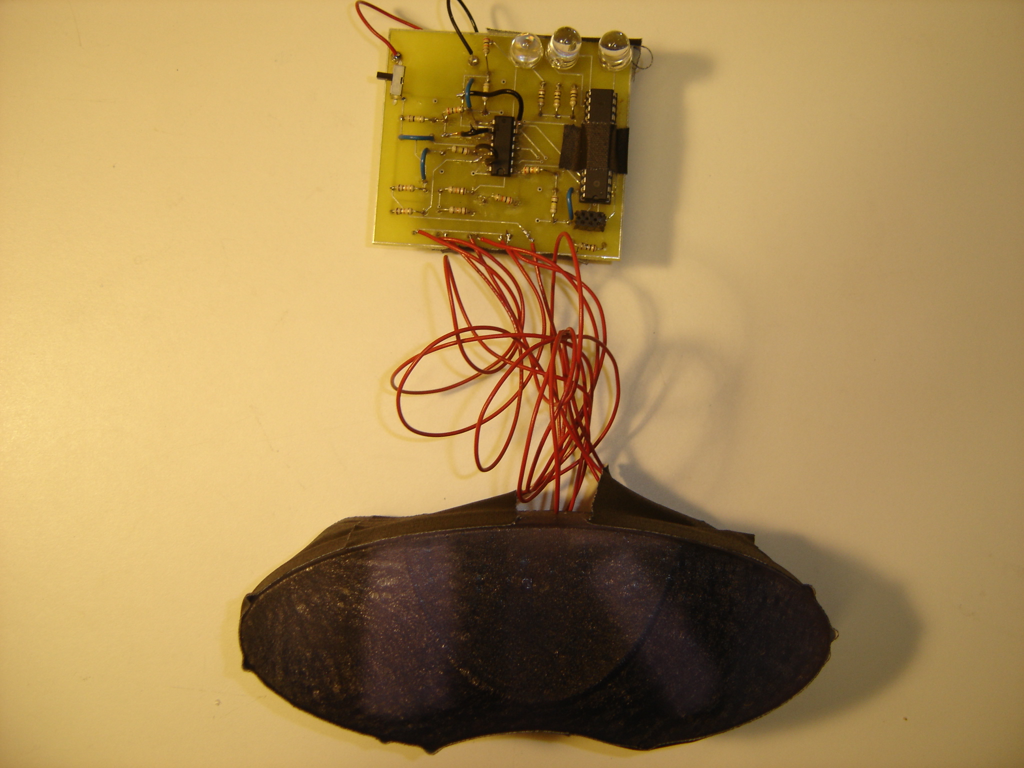
Overall, I am satisfied by the development of this object. The resulting device seems sensitive and fairly intuitive in the different categories of touch that it identifies. I also feel that this project was a good exercise for me in combining several of the skills I developed during Techniques for Design and Fabrication (including microcontroller programming, design of circuit boards using Eagle, and analog electronics such as sensors and opamps) in an interesting tangible form. I would have liked the final device to be completely handheld. However, due to the size of the circuit board and the revised battery pack, this became impractical.